

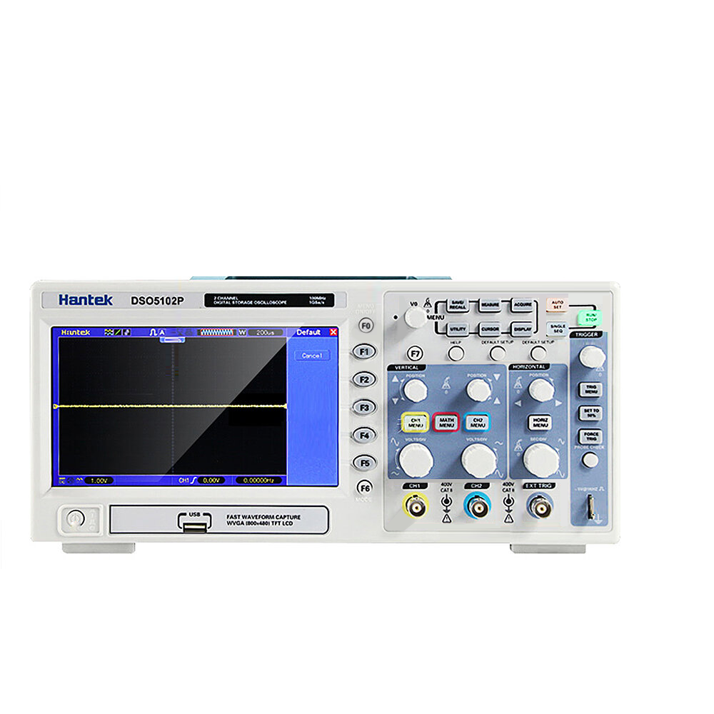

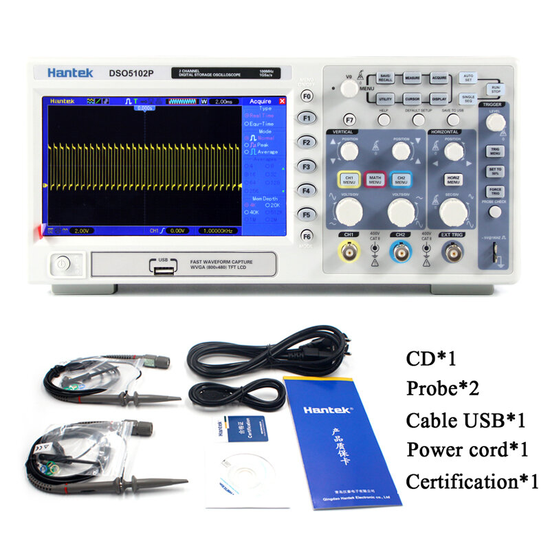

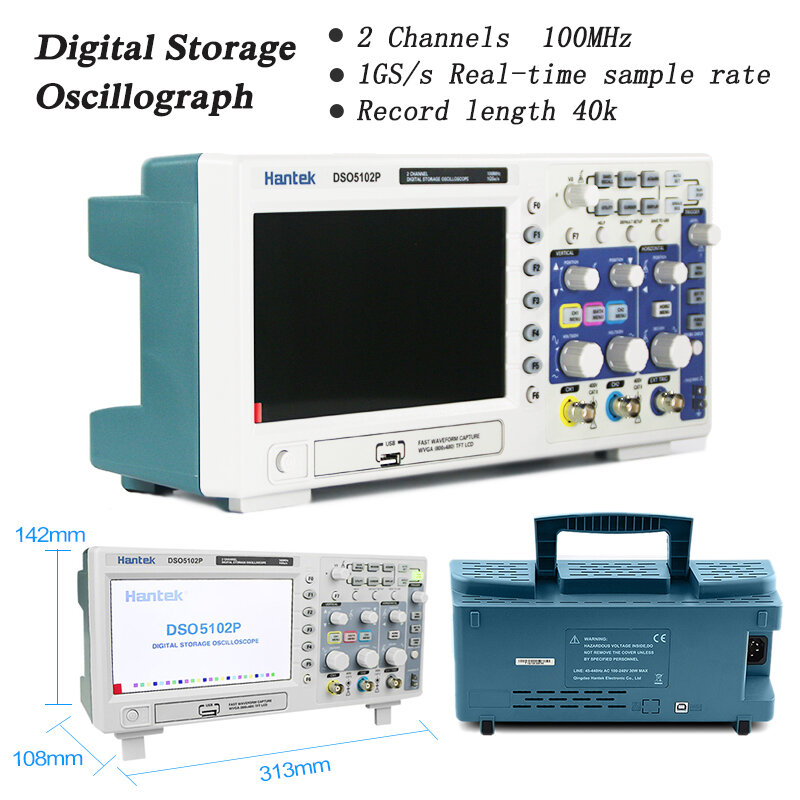
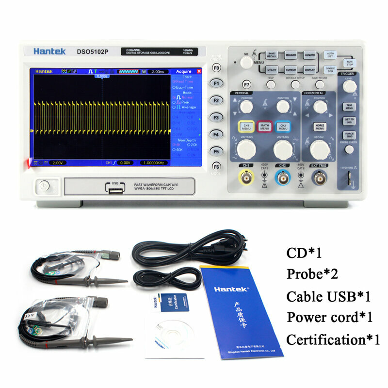


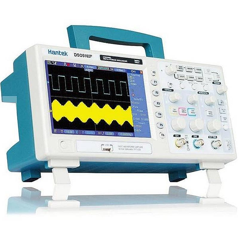
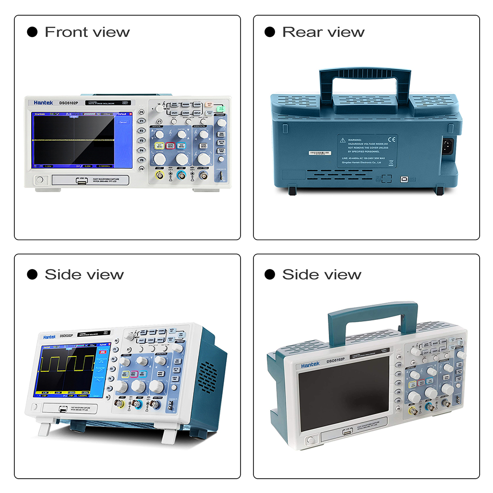
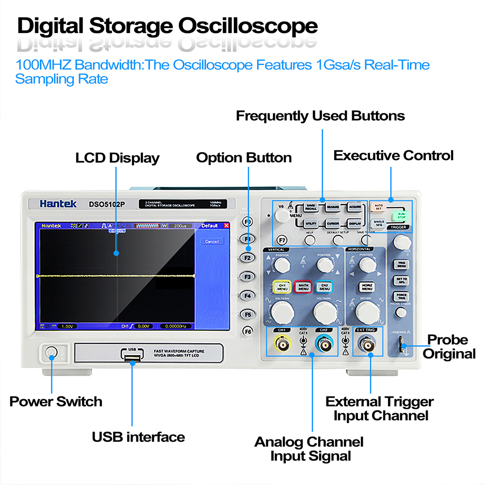
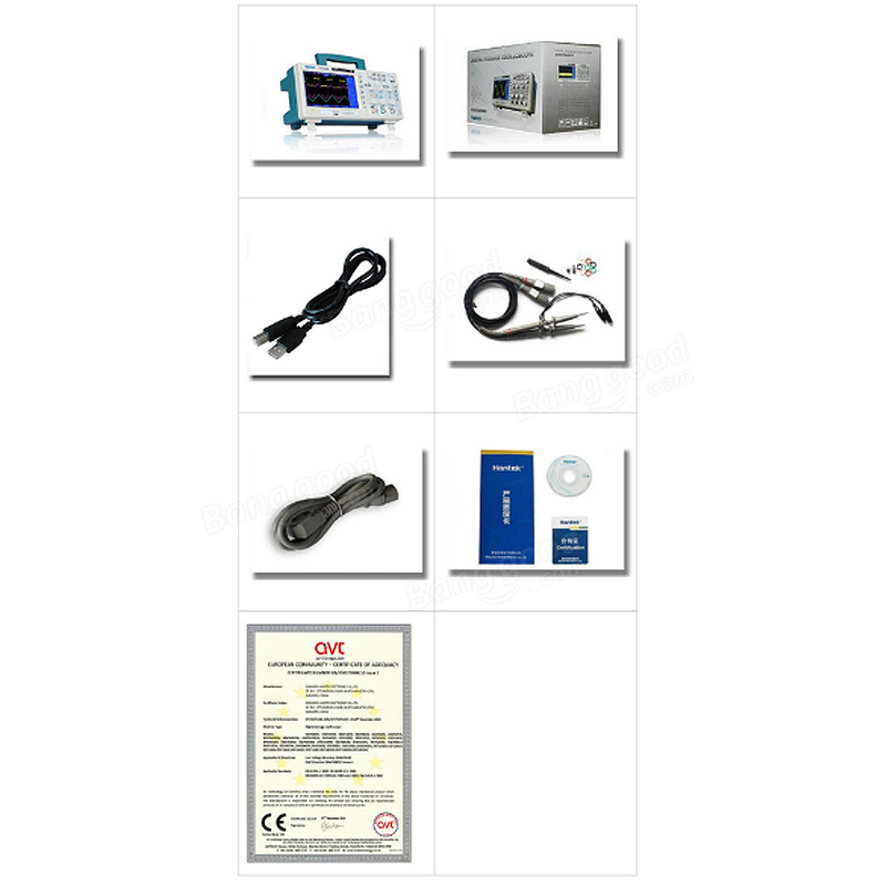
Hantek DSO5102P USB Digital Storage Oscilloscope 2Channels 100MHz 1GSa/s

 Direct purchase from the factory
सुरक्षित भुगतान

 मुफ्त उपहार
 शिपिंग नीति
 रिटर्न नीति
मुफ्त उपहार
Roymall में आपका स्वागत है, प्रीमियम उपहार की आपकी दुकान। हम आपके समर्थन की सराहना करते हैं और आभार के रूप में हर खरीद पर मुफ्त उपहार प्रदान करते हैं। हमारे संग्रह को देखने के लिए तैयार हैं? हमारे चयन को ब्राउज़ करें, अपना ऑर्डर दें और अपने खरीद के साथ मुफ्त उपहार प्राप्त करें।शिपिंग नीति
हम ऑर्डर 2 दिन में संसाधित करते हैं।सामान्य शिपिंग समय 5-7 कार्य दिवस है।गंतव्य के आधार पर शिपिंग समय अलग हो सकता है।1. रिटर्न नीति
हम केवल roymall.com से खरीदल गइल आइटम स्वीकार करत बानी। मुफ्त उपहार रिटर्न ना कइल जा सके। रिटर्न कइल जाए वाला आइटम अप्रयुक्त और मूल पैकेजिंग में होन चाहीं।हम रिटर्न 3-5 कार्य दिवस में संसाधित करत बानी।कस्टम आइटम रिटर्न ना कइल जा सके।संपर्क करीं: service@roymall.com या Whatsapp: +86193598494712.धन वापसी नीति
रिटर्न आइटम मिले के बाद पूरा धन वापस मिली। शिपिंग लागत वापस ना मिली।संपर्क करीं: service@roymall.com या Whatsapp: +8619359849471Feature:
200/100/70MHz bandwidths
1GSa/s Real Time sample rate
Large (7.0-inch) color display, WVGA(800x480)
Record length up to 40K
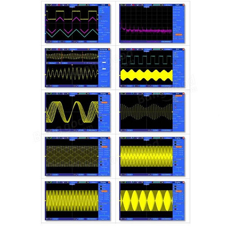
Trigger mode: edge/pulse width/line selectable video/slop/overtime etc.
USB host and device connectivity, standard
Multiple automatic measurements
Four math functions, including FFTs standard
Provides software for PC real-time analysis
Model
DSO5102P
Acquisition
Sample Rate
Real-Time Sample: 1GS/s
Acquisition Modes
Normal
Normal data only
Peak Detect
High-frequency and randon glith capture
Average
Wavefom Average, selectable 4,8,16,32,64,128
Inputs
Inputs Coupling
AC, DC, GND
Inputs Impendance
1Mu03a9u00b12%u201620pFu00b13pF
Probe Attenuation
1X, 10X
Supported Probe Attenuation Factor
1X, 10X, 100X, 1000X
Maximum Input Voltage
CAT I and CAT II: 300VRMS (10u00d7), Installation Category;
CAT III: 150VRMS (1u00d7);
Installation Category II: derate at 20dB/decade above 100kHz to 13V peak AC at 3MHz* and above. For non-sinusoidal waveforms, peak value must be less than 450V. Excursion above 300V should be of less than 100ms duration. RMS signal level including all DC components removed through AC coupling must be limited to 300V. If these values are exceeded, damage to the oscilloscope may occur.Horizontal System
Sample Rate Range
500MS/s--1GS/s
Waveform Interpolation
(sin x)/x
Record Length
40K
SEC/DIV Range
4ns/div to 40s/div
Sample Rate and
Delay Time Accuracyu00b150ppm(at over any u22651ms time interval)
Position Range
20ns/div to 80us/div; (-8div x s/div) to 40ms;
200us/div to 40s/div; (-8div x s/div) to 400sTime Measurement Accuracy
(Full Bandwidth)Single-shot, Normal mode:u00b1 (1 sample interval +100ppm u00d7 reading + 0.6ns);
>16 averages:u00b1 (1 sample interval + 100ppm u00d7 reading + 0.4ns);
Sample interval = s/div u00f7 200Vertical System
Vertical Resolution
8-bit resolution, all channel sampled simultaneously
Position Range
2mV/div to 10V/div
Bandwidth
100MHz
Rise Time at BNC( typical)
3.5ns
Analog Bandwidth in Normal and Average modes at BNC or with probe, DC Coupled
2mV/div to 20mV/div, u00b1400mV; 50mV/div to 200mV/div, u00b12V
500mV/div to 2V/div, u00b140V; 5V/div, u00b150VMath
+, -, *, /, FFT
FFT
Windows: Hanning, Flatop, Rectamgular, Bartlett, Blackman;
1024 sample pointBandwidth Limit
20MHz
Low Frequency Response (-3db)
u226410Hz at BNC
DC Gain Accuracy
u00b13% for Normal or Average acquisition mode, 5V/div to 10mV/div;
u00b14% for Normal or Average acquisition mode, 5mV/div to 2mV/divDC Measurement Accuracy,
Average Acquisition ModeWhen vertical displacement is zero, and N u226516:u00b1 (3% u00d7 reading + 0.1div + 1mV) only 10mV/div or greater is selected;
When vertical displacement is not zero, and Nu226516: u00b1 [3% u00d7 (reading + vertical position) + 1% of vertical position + 0.2div]; Add 2mV for settings from 2mV/div to 200mV/div; add 50mV for settings from 200mV/div to 5V/divVolts Measurement Repeatability,
Average Acquisition Modevolts between any two averages of u226516 waveforms acquired under same setup and ambient conditions
Trigger System
Trigger Types
Edge, Video, Pulse, Slope, Over time, Alternative
Trigger Source
CH1, CH2, EXT, EXT/5, AC Line
Trigger Modes
Auto, Normal, Single
Coupling Type
DC, AC, Noise Reject, HF Reject, LF Reject
Trigger Sensitivity
(Edge Trigger Type)DC(CH1,CH2):
1div from DC to 10MHz; 1.5div from 10MHz to 100MHz; 2div from 100MHz to Full;
DC(EXT):
200mV from DC to 100MHz; 350mV from 100MHz to 200MHz;
DC(EXT/5):
1V from DC to 100MHz;1.75V from 100MHz to 200MHz;
AC: Attenuates signals below 10Hz;
HF Reject: Attenuates signals above 80kHz
LF Reject: Same as the DC-coupled limits for frequencies above 150kHz; attenuates signals below 150kHzTrigger Level Range
CH1/CH2: u00b18 divisions from center of screen;
EXT: u00b11.2V;
EXT/5:u00b16VTrigger Level Accuracy( typical)Accuracy is for signals having rise and fall times u226520ns
CH1/CH2: 0.2div u00d7 volts/div within u00b14 divisions from center of screen;
EXT: u00b1 (6% of setting + 40mV);
EXT/5: u00b1 (6% of setting + 200mV);Set Level to 50%(typical)
Operates with input signals u226550Hz
Video Trigger
Video Trigger Type
CH1, CH2: Peak-to-peak amplitude of 2 divisions;
EXT: 400mV;
EXT/5: 2VSignal Formats and Field Rates, Video Trigger Type
Supports NTSC, PAL and SECAM broadcast systems for any field or any line
Holdoff Range
100ns ~ 10s
Pulse Width Trigger
Pulse Width Trigger Mode
Trigger when (< , >, = , or u2260); Positive pulse or Negative pulse
Pulse Width Trigger Point
Equal: The oscilloscope triggers when the trailing edge of the pulse crosses the trigger level.
Not Equal: If the pulse is narrower than the specified width, the trigger point is the trailing edge. Otherwise, the oscilloscope triggers when a pulse continues longer than the time specified as the Pulse Width.
Less than: The trigger point is the trailing edge.
Greater than (also called overtime trigger): The oscilloscope triggers when a pulse continues longer than the time specified as the Pulse WidthPulse Width Range
20ns ~ 10s
Slope Trigger
Slope Trigger Mode
Trigger when (< , > , = , or u2260 ); Positive slope or Negative slope
Slope Trigger Point
Equal: The oscilloscope triggers when the waveform slope is equal to the set slope.
Not Equal: The oscilloscope triggers when the waveform slope is not equal to the set slope.
Less than: The oscilloscope triggers when the waveform slope is less than the set slope.
Greater than: The oscilloscope triggers when the waveform slope is greater than the set slope.Time Range
20ns ~ 10s
Overtime Trigger
Over Time Mode
Rising edge or Falling edge
Time Range
20ns ~ 10s
Alternative Trigger
Trigger on CH1
Internal Trigger: Edge, Pulse Width, Video, Slope
Trigger on CH2


नवीनतम खबर और पहले ऑर्डर पर 15% छूट पावीं।


 मुद्रा चुनीं
 भाषा चुनीं
लिंक:
भाषा चुनीं
लिंक: